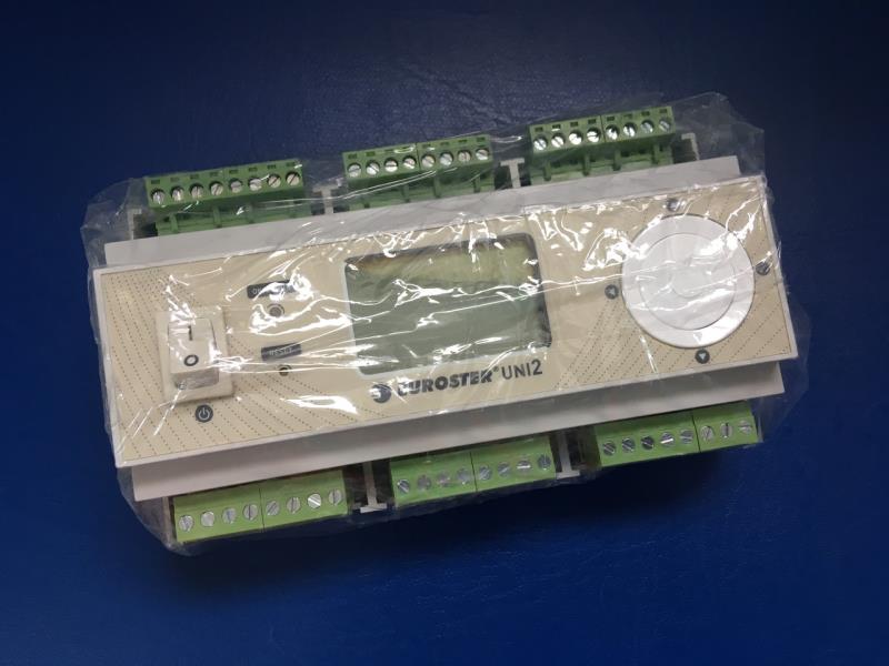
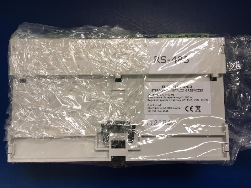
Description Euroster UNI 2 - universal weather-dependent heating circuit controller
UNI 2 is a universal controller for heating installations with:
- two central heating circuits with mixing valves (for example, for heating radiators and underfloor heating)
- hot water supply circuit
- DHW circulation circuit
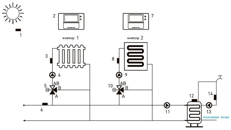
1. Outside temperature sensor
2. Room controller circuit 1
3. Circuit temperature sensor 1
4. Central heating pump circuit 1
5. Contour mixer 1
6. Supply temperature sensor
7. Room controller circuit 2
8. Temperature sensor circuit 2
9. Central heating pump circuit 2
10. Contour mixer 2
11. DHW tank charging pump
12. DHW tank temperature sensor
13. DHW circulation pump
14. DHW circulation temperature sensor
TECHNICAL PARAMETERS
- Power supply: 230 V/ 50 Hz
- Maximum power consumption: 4 W
- Maximum output load: 100 W (each output)
- Temperature adjustment range:
- - central heating circuits: from 15°C to 90°C
- - DHW circuit: from 40°C to 75°C
- - DHW circulation circuit: from 20°C to 50°C
- Temperature measurement range: from -30°C to 120°C
- Temperature adjustment and display accuracy: 1°C
- Operating temperature range: 0-40°C
- Storage temperature range: 0-55°C
- Protection class: IP20, protection class II
- Color: gray, RAL7035
- Mounting method: on a 35 mm DIN rail, mounted in a protective cabinet
- Alarm output: 230 V/ 50 Hz
- Boiler Output: Voltage-free, normally open/closed
- Power outputs for pumps: 230 V/ 50 Hz
- Power outputs for mixer servomotors: 230 V/ 50 Hz
- Controller weight: 545g
DELIVERY KIT
- UNI2 Command Controller
- External temperature sensor (5m)
- Supply temperature sensor (1.5 m)
- DHW tank temperature sensor (2.5 m)
- Circulation temperature sensor (2.5 m)
- Central heating circuit temperature sensor x2 (1.5 m)
- Sensor strips (5 pcs.)
- Expansion dowels for external temperature sensor – 2 pcs.
- User manual with warranty card
- Power cord (1.5m)
FUNCTIONS
Contours of the central heating system
- independent temperature and weather curve settings for each circuit
- independent control of each circuit using a room regulator and a weekly schedule
- the ability to turn off the circuit and the heating season
- the ability to control the circuit, at the user's discretion: by turning the pump on and off or by adjusting the mixer temperature
- interaction with underfloor heating distributors.
DHW circuit
- weekly schedule management
- DHW priority
- function of disinfection of hot water supply circuits.
DHW circulation circuit
- weekly schedule management
- time or temperature control of the circuit.
User-defined functions
- control output for a gas boiler or other heating equipment (voltage-free relay contacts)
- alarm output (230V output)
- state register (the controller remembers the last 100 states)
- many programming languages
- ability to test outputs
- overheating protection
- interaction with installations with increased supply temperatures (up to 120°C) – at the customer’s request
- frost protection
Main display
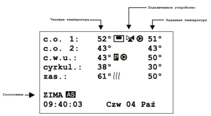
The main display shows the following information: circuit temperature: current and set (e.g. calculated by a weather algorithm) switched on equipment (pump, mixer, boiler) controller status (anti-stop, disinfection, heating season: WINTER/SUMMER, etc.) time (hour) and date.
Appearance of an example display and its description:
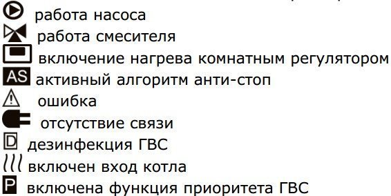
Meaning of symbols on the controller display:
Multifunctional rotary controller
The controller is operated using a multifunctional rotary control. In addition to the rotary dial for changing the set value, it contains four navigation buttons (switching between Menu positions: up, down,
next and previous Menu), as well as a confirmation button located in the middle of the rotary control.
LED
On the left side of the display is an LED. Its colors indicate the following states:
- green: Working, no errors
- red: Error
- blue: Active Menu
- yellow: Output test mode
List display
The controller settings are arranged hierarchically, starting from the "Contour" menu and continuing to the "Parameters" menu. Only basic settings are accessible to the user. Advanced options are located in the "Settings" section and are protected by an access code.
INSTALLATION
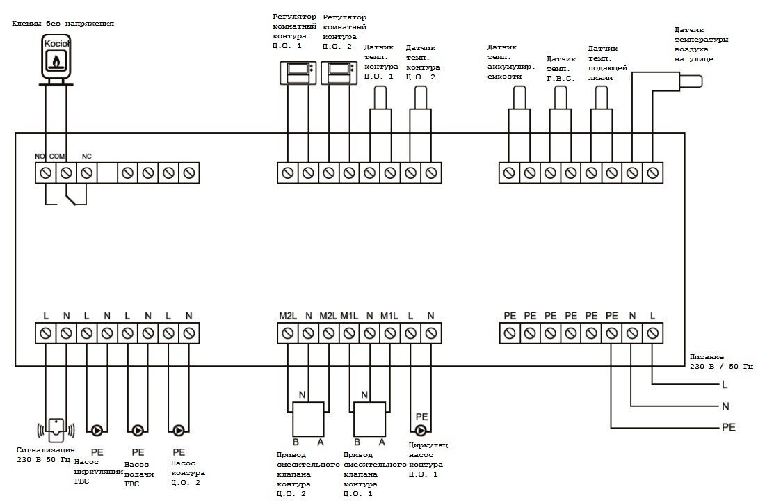
The controller should be mounted in a location where the temperature does not exceed 40°C. Before mounting the controller, all necessary wiring must be connected. The controller is designed for mounting on a 35 mm DIN rail. It is recommended to install the controller in a protective cabinet. The electrical wires should be screwed to the electrical boxes as described and shown in the following figure, observing the appropriate wire designations. Neutral wires should be screwed to the N terminals, phase wires to the L terminals, and protective wires to the PE terminals. For connections, use a wire with a minimum cross-section of 0.75 mm. The controller is equipped with six temperature sensors. Deactivated circuits and functions do not require connection of the sensors. The sensors can be connected to the controller in any manner, without the need to ensure wire polarization. During installation, avoid placing the sensor parallel to live electrical wires. Ensure proper contact with the measured surfaces. Mount the outside temperature sensor in a shady location out of direct sunlight, away from windows and doors, at a height of approximately 2 meters above the ground. Similarly, the room thermostat can be turned on or off for each heating circuit.
Only regulators with a voltage-free normally open (NO) contact may be used. Euroster regulators are recommended.
Connection diagram:
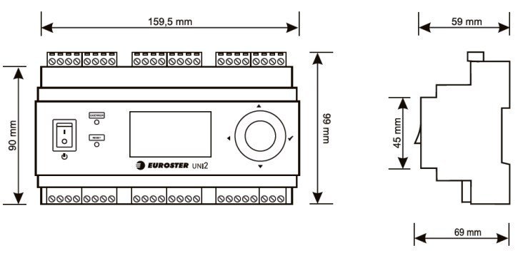
DIMENSIONS